How to setup File Server with Raspberry Pi

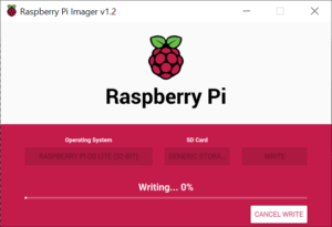
We are gonna kick off with preparing fresh copy of Raspberry PI OS Lite on empty SD card with Raspberry Pi Imager software. When is all done SD card has to be removed and inserted back into card reader so Windows can see newly created partition. In my case i’m using Notepadd++ to create empty file called “SSH” without file extension and we are gonna save it to boot partition of our SD card.

Because SSH is enabled with placing empty file called SSH in root partition of SD card, we do not need to connect Monitor, Keyboard and  Mouse to our Raspberry Pi. We are gonna be using SSH connection from another computer or even from another Raspberry Pi. From Windows computer we can use PuTTY software and from Linux computer we can to simply from terminal window.
Before we power on our Raspberry Pi, we need to insert SD card into Raspberry Pi,  connect LAN cable to network Router, connect USB hard drive and we are ready to power up Raspberry Pi.
Next step is to find out IP address of our future File Server. Because we didn’t connect monitor to our File Server, the best way to find it is to login into Router and from there read IP address of our File Server.
I’m using Linux terminal for connection to server, but once you are connected commands are the same from Linux or Windows.
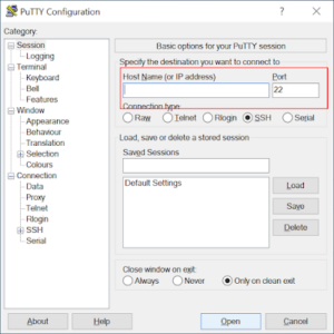
To connect from Windows, we need to open the PuTTY software, enter IP address of our File Server and click on Open button.
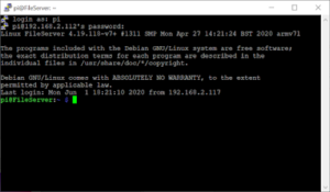
In the next Window we need to enter valid username and password. Default username for Raspberry Pi OS is “pi” and password “raspberry”.
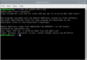
For Linux computer we need to just open terminal and enter command:
sudo ssh pi@IP_Address
and when asked enter valid password and we are connected. Now we are ready to make necessary changes to our File Server system and install necessary software.
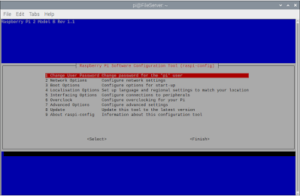
So let’s get started, first we are gonna open raspi config software by typing:

    sudo raspi-config

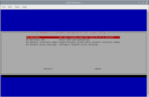
First option is to change password for “pi” user, so here we can set desired password. Next under Network Options we are gonna change default hostname to our needs, i personally like to change it to “FileServer”.
After changing Hostname, raspi-config software is gonna ask to reboot our new File Server.
In next step we have to login an update our Raspberry Pi OS on our FileServer, so to do that we are gonna enter next two command:
sudo apt update
sudo apt upgrade
Create folder for mounting our USB drive:
sudo mkdir -m 1777 /media/USB_Drive
Edit “fstab” file and add mount point for our USB Drive:
sudo nano /etc/fstab
Add at end of file next line for ntfs formated hard drive:
/dev/sda1    /media/USB_Drive    ntfs    defaults    0    1
Save changes and mount partition with next command:
sudo mount -a
Install samba server:
sudo apt install samba samba-common-bin
Edit samba config and add our share at end of file:

sudo nano /etc/samba/smb.conf

[Network share]

  comment = Network shared folder

       path = /media/USB_Drive
       browseable = yes
       writable = yes
       only guest = no
       create mask = 0777
       directory mask = 0777
       public = yes
       guest ok = yes

Add pi user to samba and set password:
sudo smbpasswd -a pi
Restart samba service:
sudo service smbd restart
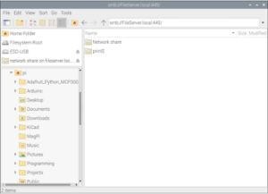
And with restarting samba service we are ready to open File Manager and browse our FileServer.
So from now on our server is ready to go, even if you turn off Raspberry Pi, everything is starting automatically with booting Raspberry Pi OS.
Thanks for visiting!
Till the next time.
How to make a fresh copy of micro SD card for Raspberry Pi from Windows 10 operating system

In this article, I will explain how to prepare a micro SD card from Windows 10 with a fresh copy of Raspberry Pi OS, so let’s start:

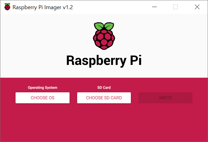
The first step is to refer the web browser to the official website raspberrypi.org and download the Raspberry Pi Imager software, which we will use to prepare a micro SD card for installing the Raspberry Pi OS on a Raspberry PI computer.

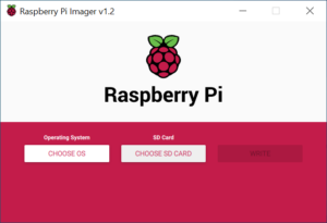
  • Open the Raspberry Pi Imager software on your Windows 10 computer.
  • Click the CHOOSE OS button.
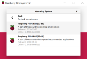
  • Select the version of the OS you want to install.
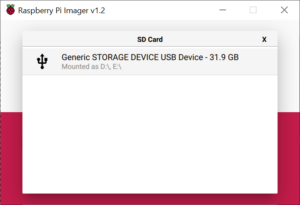
  • Click the CHOOSE SD CARD button.
  • Select the SD card, which you want to prepare for the installation of the Raspberry Pi OS.
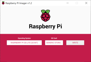
  • Click on WRITE button to start writing to SD card.
  • Wait until writing is complete.

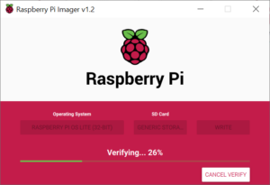
  • Wait a little bit more, until the written data is verified.
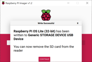
  • Clicking the DONE button completes the SD card preparation.
And all we have to do is insert the SD card into the Raspberry Pi and install the Raspberry Pi OS.
Until next time, thanks for visiting!

Raspberry Pi 4 Native USB Boot

It has finally arrived, unfortunately in beta but it still works, RPi 4 Native USB Boot. Say goodby to micro SD. I have been using RPi 4 for about four months or a little more, as a personal computer and I am mostly satisfied. Settings “boot” partition on micro SD card and “root” partition on
SD disk, works without any problems. But recently it has been possible to set up RPi 4 to boot directly from a USB drive!
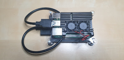
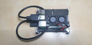
My RPi 4 Setup (RPi 4, 4GB, Samsung SSD 250GB, USB to S-ATA adapter, sertronic RPI4-ARC-FA case with cooler)

First I found a video on Youtube and tried to make it and I failed. Then an article came out on the portal, so I followed the instructions and again I failed. 
Opsss! What is happening? 
I used NOOBS for OS instead of Raspbian (oooo noooo). So I came to the conclusion that Native USB Boot does not work on NOOBS.
The following is a step-by-step guide on how to set up RPi 4 for Native USB Boot, or to Boot without micro SD.
So let’s get started:
  1. make a fresh copy of micro SD with Raspbian OS (Raspbian Imager, works on Windows, Linux and macOS)
  2. insert micro SD into RPi4 and power on
  3. install OS
  4. update OS:
    • sudo apt update
    • sudo apt full-upgrade
    • sudo rpi-update
  5. reboot RPi
  6. edit rpi-eeprom-update:
    • sudo nano /etc/default/rpi-eeprom-update
    • FIRMWARE_RELEASE_STATUS value from “critical” to “beta”
  7. update firmware:
    • sudo rpi-eeprom-update -d -f /lib/firmware/raspberrypi/bootloader/beta/pieeprom-2020-05-15.bin
  8. reboot RPi
  9. check firmware version:
    • vcgencmd bootloader_version
  10. clone micro SD to USB Drive (SD Card Copier)
  11. shutdown RPi
  12. remove micro SD
  13. power on RPi
And that should be it, now we have an RPi with an SSD that is significantly faster than a micro SD. Lots of fun and I hope this step by step guide is helpful.
Until next time, Thanks for visiting!

Power supply unit, variable triple output

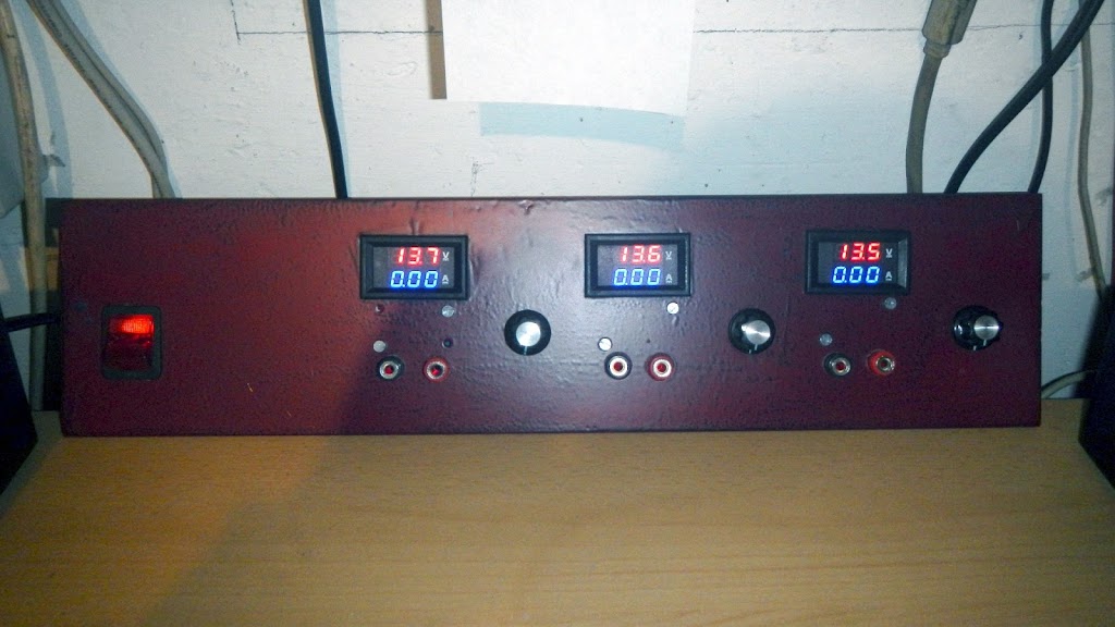
Today I finished the project, which I started a few months ago. Three channel desktop power supply with the adjustable output voltage. In the future, I would like to add control of the current limit, but I will talk about it on another occasion.

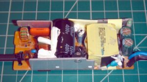
I used two adapters, from older laptops to convert AC voltage to DC. One gives 15V DC output (a little strange output, the laptop mostly uses 19V DC, but that’s what I had, so I wanted to use it) and the other gives 19V DC.

Adapter from an old laptop, AC-DC converter
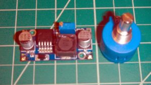
Further on, I used DC to DC (HW-411) modules purchased on eBay and 10-turn potentiometers for voltage regulation from 1.25V to 13.5V. The HW-411 is a DC-DC module with an integrated LM2596 circuit and comes with a built-in trimmer potentiometer for adjusting the output voltage. To install a 10-turn potentiometer, remove the trimmer potentiometer so that we can install a 10-turn potentiometer.
HW-411 (LM2596) DC-DC Module and 10-Turn Potentiometer
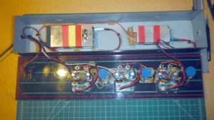
So I used three such modules and placed them on the front panel together with the panel meters, the binding post and the switch to power ON or OFF.
This is how it looks from the inside:
And that would be it, I wanted to show you how you can easily do this yourself with little effort and use old devices that usually collect dust in many homes or end up in the garbage and can still be useful.
If you choose to do this kind of device yourself, do so at your own risk. Be careful, such a device is connected to mains voltage, which can be very dangerous if you are not an expert.
All comments are welcome, thank you for visiting!

Peak voltage detector for a sine wave generator

I recently built a 1kHz sine waveform generator, the device works great, has adjustable amplitude and is suitable for testing audio amplifiers and for repairing them. So I thought it would be nice if I could install a small panel voltmeter to display the output voltage.

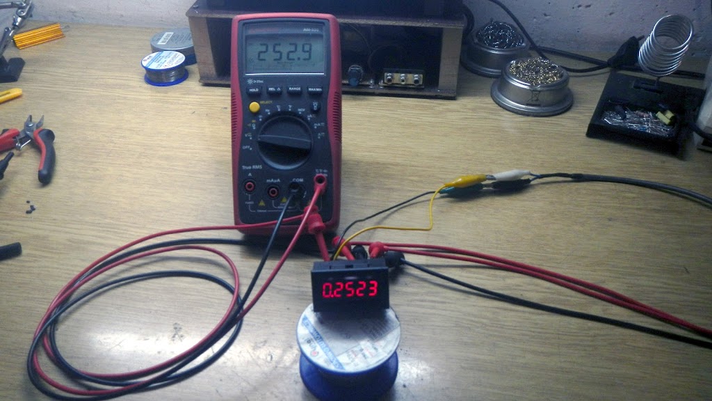
Through eBay, I bought five voltmeters and two of them stopped working, so I decided to investigate what happened to them and try to install one of them into the sine waveform generator.
The 3.6V voltage regulator on the voltmeter itself was blown. So I removed the voltage regulator and instead of its output pin, I connected the wire to which I connected the 3.6V voltage and the voltmeter woke up.
But that’s not all, to use this kind of voltmeter to measure the voltage of the sine wave, the voltage needs to be rectified into the DC.
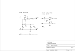
The best way to do this is by making a peak voltage detector, we can do this with uA741.
Peak voltage detector and 3.6V voltage regulator
The device works fine but has a disadvantage, it only shows a positive peak voltage so that the voltage displayed on the voltmeter. For now, I will leave the device as it is, but in the future, I plan to make a device that will spin the peak voltage of the positive and negative peak.
All comments are welcome, Thank’s for visiting!

Arduino, two channel voltmeter with thermometer

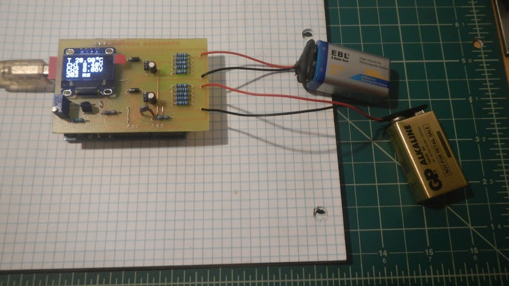
This is my new Arduino project, a two-channel voltmeter with a thermometer.
This device uses Arduino’s 10-bit analog-to-digital converter, software oversampled to 12-bit and every four measurements are added to the average value. This measured value is printed on the display every 300 milliseconds.

The scheme is not professionally and aesthetically drawn, I apologize in advance if it is unknowingly unreadable. So I will try to explain how the device works and where the input signal goes.
The measured voltage is applied to the input CH1 + and CH1 terminals. There are 5 resistors at the input, giving us a ratio of 10/1, which allows us to measure 40VDC voltages. The output of the voltage divide leads to the filter capacitor and protection diodes, and then to the Arduino A1 pin to be able to convert to digital format and print in the display. The same goes for channel two.
For the voltage reference, I used the TL431, which is set to give 4.096 VDC voltage and is connected to the Arduino AREF pin.
Temperature measurement was performed by a thermistor. The resistor and thermistor that are connected to the series are a voltage divider with the variable output voltage. The output is connected to the Arduino A0 pin to convert the analog value into a digital format.
The OLED display is simply connected to + 5V and GND, and signing lines SDA and SCL, to the appropriate Arduino pin.
Arduino sketch for this two-channel Voltmeter
// *********************************************************
// Program:   two chanel voltmeter with thermometer
// Date:      01/09/2018
// Version:   1.0
// Author:    Elvis Baketa
// Description: 
// *********************************************************

#include <Arduino.h>
#include <Wire.h>
#include <U8g2lib.h>

// WHITE OLED LCD 0.96" 128X64 I2C
U8G2_SSD1306_128X64_NONAME_F_HW_I2C u8g2(U8G2_R0, /* reset=*/ U8X8_PIN_NONE);

unsigned long startTime;
unsigned long finishTime;

int updateDisplay = 0;
int samples = 16;
float resolution = 4096.0;
float voltageReference = 4.096;
float seriesResistor = 47000.00;

int analogValueCH0[16];
int analogValueCH1[16];
int analogValueCH2[16];
unsigned int averageAnalogValueCH0;
unsigned int averageAnalogValueCH1;
unsigned int averageAnalogValueCH2;
float voltageCH0 = 0.000;
float voltageCH1 = 0.000;
float voltageCH2 = 0.000;
float averageVoltageCH1 = 0.000;
float averageVoltageCH2 = 0.000;

float resistance = 0.000;
float temperature = 0.000;
float averageTemperature = 0.000;

void setup() {
  // put your setup code here, to run once:
  analogReference(EXTERNAL);
  u8g2.begin();
}

void loop() {
  // put your main code here, to run repeatedly:
  updateDisplay++;
  
  // read chanel one
  for(int i = 0; i < samples; i++) {
    analogValueCH0[i] = analogRead(A0);
    delay(1);
  }
  for(int l = 0; l < samples; l++) {
    averageAnalogValueCH0 += analogValueCH0[l];
  }
  averageAnalogValueCH0 /= 4;
  voltageCH0 = averageAnalogValueCH0 * (voltageReference / resolution);
  averageAnalogValueCH0 = 0;
  // convert volts to resistance
  resistance = voltageReference / voltageCH0 - 1;
  resistance = 1 / resistance;
  resistance = seriesResistor * resistance;
  // convert resistance to temperature in Kelvin
  temperature = log(resistance / seriesResistor);
  temperature = temperature * (1 / float(3435));
  temperature = temperature + (1 / (25 + 273.15));
  temperature = 1 / temperature;
  // convert Kelvin to Celsius
  // T(°C) = T(°K) - 273.15
  temperature = temperature - 273.15;
  averageTemperature += temperature;
  
  // read chanel two
  for(int j = 0; j < samples; j++) {
    analogValueCH1[j] = analogRead(A1);
    delay(1);
  }
  for(int m = 0; m < samples; m++) {
    averageAnalogValueCH1 += analogValueCH1[m];
  }
  averageAnalogValueCH1 /= 4;
  voltageCH1 = averageAnalogValueCH1 * (voltageReference / resolution);
  voltageCH1 *= 10;
  averageVoltageCH1 += voltageCH1;
  averageAnalogValueCH1 = 0;
  
  // read chanel three
  for(int k = 0; k < samples; k++) {
    analogValueCH2[k] = analogRead(A2);
    delay(1);
  }
  for(int n = 0; n < samples; n++) {
    averageAnalogValueCH2 += analogValueCH2[n];
  }
  averageAnalogValueCH2 /= 4;
  voltageCH2 = averageAnalogValueCH2 * (voltageReference / resolution);
  voltageCH2 *= 10;
  averageVoltageCH2 += voltageCH2;
  averageAnalogValueCH2 = 0;

  if(updateDisplay > 4) {
    // display data
    u8g2.clearBuffer();
    u8g2.setFont(u8g2_font_profont22_tf);
    averageTemperature /= updateDisplay;
    u8g2.setCursor(0, 16);
    u8g2.print("T ");
    u8g2.print(averageTemperature);
    u8g2.print(char(176));
    u8g2.print("C");
    averageVoltageCH1 /= updateDisplay;
    u8g2.setCursor(0, 32);
    u8g2.print("CH1 ");
    u8g2.print(averageVoltageCH1);
    u8g2.print("V");
    averageVoltageCH2 /= updateDisplay;
    u8g2.setCursor(0, 48);
    u8g2.print("CH2 ");
    u8g2.print(averageVoltageCH2);
    u8g2.print("V");
    u8g2.setCursor(0, 64);
    finishTime = millis() - startTime;
    u8g2.print(finishTime);
    u8g2.print(" ms");
    u8g2.sendBuffer();
    averageTemperature = 0.000;
    averageVoltageCH1 = 0.000;
    averageVoltageCH2 = 0.000;
    updateDisplay = 0;
    startTime = millis();
  }
}
Here you can download Arduino sketch and Eagle PCB files to make this device.
All comments are welcome, Thank’s for visiting!

RC Filter Calculator (low-pass and high-pass)


RC Filter Calculator

Here is simple RC filter calculator for calculatie cut-off frequency of a low-pass and high-pass rc filter:

RC Filter Calculator v1.0
R = Ohm
C = Fahrad
f = Hertz

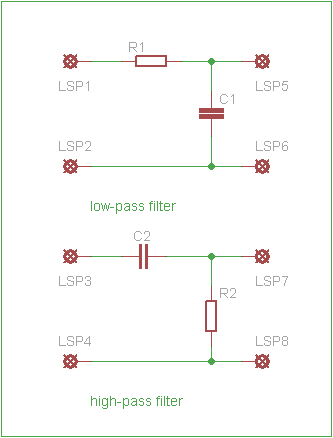
low-pass filter is a filter that passes signals with a frequency lower than a certain cutoff frequency and attenuates signals with frequencies higher than the cutoff frequency.
high-pass filter is an electronic filter that passes signals with a frequency higher than a certain cutoff frequency and attenuates signals with frequencies lower than the cutoff frequency.

More about low-pass and high-pass filer can be found on wikipedia.