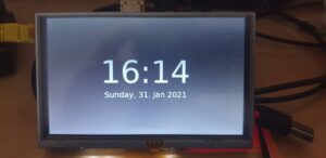
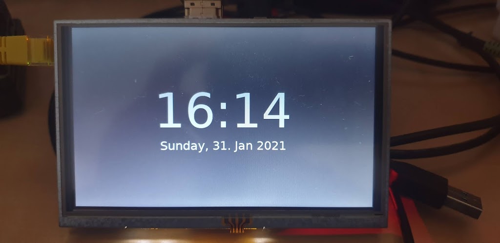
Raspberry Pi Digital Clock, written in Python programming language

This was challenging for me to get into Python programming and setting Raspberry Pi to my own needs. I know this is overkill but also this is a path for future projects for example info display which can display time, the temperature in your place, and maybe turn on lights in the living room and the list goes on and on.

Hardware requirements:

Raspberry Pi
Waveshare 5inch HDMI LCD
MicroSD Card
PSU for Raspberry Pi

1. create micro sd card with raspberry pi os lite

Here we need to enter the path and name of the image we want to write to the sd card instead of “/ source_image_file” and instead of “/ destination_disk_drive” we need to enter the path and name of the disk we want to write to.

sudo dd if=/source_image_file of=/destination_disk_drive

2. enable SSH

To be able to access over SSH we need to create an empty file named SSH in the boot partition of our Micro SD card.

sudo touch /media/your_username/boot/SSH

3. setup hostname

sudo nano /media/ebaketa/rootfs/etc/hostname

4. edit the host’s file and replace “myhostname” with the desired hostname:

sudo nano /media/your_username/rootfs/etc/hosts

127.0.0.1	localhost
::1		localhost
127.0.1.1	myhostname.localdomain	myhostname

5. setup a static IP address

sudo nano /media/your_username/rootfs/etc/dhcpcd.conf

# Example static IP configuration:
interface eth0
static ip_address=192.168.x.xxx/24
#static ip6_address=fd51:42f8:caae:d92e::ff/64
static routers=192.168.x.x
static domain_name_servers=192.168.x.x 8.8.8.8 fd51:42f8:caae:d92e::1

6. edit Raspberry Pi OS configuration file config.txt

These lines below we need to add to “config.txt” to configure 5 inch HDMI LCD. The best is to add lines to the end of the file.

max_usb_current=1
hdmi_group=2
hdmi_mode=87
hdmi_cvt 800 480 60 6 0 0 0
hdmi_drive=1

7. insert micro SD to the target machine, boot OS, and login over SSH

Now we can insert an SD card into Raspberry Pi, connect the power supply and boot into OS.

8. update Raspberry Pi OS

sudo apt update
sudo apt upgrade

9. reboot Raspberry Pi OS and login over SSH

10. start raspi-config tool

sudo raspi-config

change default password
set boot options -> console autologin
set language and regional settings
set keyboarad layout
set time zone

11. reboot Raspberry Pi OS and login over SSH

12. install xorg, xinit, x11-server-utils

sudo apt -y install --no-install-recommends xserver-xorg
sudo apt -y install --no-install-recommends xinit
sudo apt -y install x11-xserver-utils

13. install openbox, lxterminal, lxtask, lxappearance

sudo apt -y install openbox obconf obmenu lxterminal lxtask lxappearance

14. install PyGObject

sudo apt -y install python-gi python-gi-cairo python3-gi python3-gi-cairo gir1.2-gtk-3.0

15. create .bash_profile file and add a line below

touch ~/.bash_profile && sudo nano ~/.bash_profile

if [[ -z $DISPLAY ]] && [[ $(tty) = /dev/tty1 ]]; then exec startx; fi

16. create openbox autostart file and add lines below

mkdir ~/.config && mkdir ~/.config/openbox && touch ~/.config/openbox/autostart && sudo nano ~/.config/openbox/autostart

# disable screen saver
xset s off &
xset s -dpms &
# run python digital clock
python ~/Projects/python/digital_clock/digital_clock.py

17. create directories for projects and get projects via wget

mkdir ~/Projects && mkdir ~/Projects/python && mkdir ~/Projects/python/digital_clock && cd ~/Projects/python/digital_clock

wget https://raw.githubusercontent.com/ebaketa/digital_clock/master/digital_clock.py

18. reboot Raspberry Pi OS

And that’s it with the next boot you should have a Raspberry Pi digital clock. If you find any mistakes in commands, please let me know, so I can correct them!

Github repo: https://github.com/ebaketa/digital_clock

Till the next time!
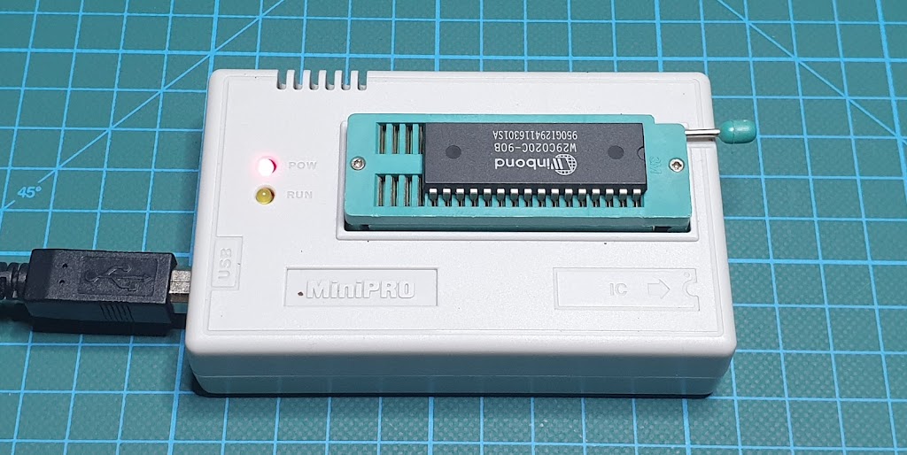
MiniPRO TL866xx universal programmer Linux installation.

The TL866A universal programmer is a chip programmer that allows us to write or read chip memory such as microcontrollers, EEPROM memory, etc. This very popular device, unfortunately, comes with software only for the Windows operating system. But there is an open-source alternative that allows the use of this device on the Linux operating system, thanks to David Griffith and his project on GitLab.


Installation:

Install build dependencies:

sudo apt install build-essential pkg-config git libusb-1.0-0-dev

Get source code:

git clone https://gitlab.com/DavidGriffith/minipro.git

Compile source code:

cd minipro
make

Install application:

sudo make install

Udev configuration:

sudo cp udev/*.rules /etc/udev/rules.d/
sudo udevadm trigger

Add regular user to the plugdev group:

sudo usermod -a -G plugdev YOUR-USER

Reboot your system.

Basic usage:

Show all available options:

minipro

Show version information:

minipro -V

Read from the device and save to a file:

minipro -p W29C020C -r test_w29c020c.bin

Erase the device:

minipro -p W29C020C -E

Blank check:

minipro -p W29C020C -b

Write from file to the device:

minipro -p W29C020C -w test_w29c020c.bin

I am very pleased with this installation, everything went without a single problem and the universal programmer works flawlessly. Many thanks to the open-source community and fingers up for David’s project on GitLab.

Stay healthy and safe till the next time!

Basic commands and using PICkit 2 on Linux!

Now that we have the software installed and ready to use, it is time to get familiar with the basic commands to successfully load the program into the microcontroller. So let’s get started!

Checking version:

pk2cmd -?V

# Returned output:

Executable Version:    1.20.00
Device File Version:   1.55.00
OS Firmware Version:   2.32.00


Operation Succeeded

Auto-detect PIC:

pk2cmd -P

# Returned output:
Auto-Detect: Found part PIC16F887.


Operation Succeeded

Erase a device:

pk2cmd -P -E

# Returned output:
Auto-Detect: Found part PIC16F887.

Erasing Device...

Operation Succeeded

Blank check:

pk2cmd -P -C

# Returned output:
Auto-Detect: Found part PIC16F887.

Device is blank

Operation Succeeded

Program a device:

pk2cmd -PPIC16F887 -J -M -Ftest_write.hex

# Returned output:
PICkit 2 Program Report       
2-1-2021, 1:17:27
Device Type: PIC16F887

Program Succeeded.

Operation Succeeded

Power a device and release reset:

pk2cmd -P -A5 -T -R

# Returned output:
Auto-Detect: Found part PIC16F887.


Operation Succeeded

Read a device:

pk2cmd -PPIC16F887 -J -R -GFtest_read.hex

# Returned output:
Read successfully.            

Operation Succeeded
I believe this is enough to get started with PICkit 2 Development Programmer / Debugger on Linux OS.
Stay healthy and safe till the next time!

Install PICkit 2 Development Programmer / Debugger on Raspberry Pi OS.

To install PICkit 2 Development Programmer / Debugger on Raspberry Pi OS, we are gonna first prepare our system by installing dependencies, download source code for PICkit 2 command-line application, compile it, and at the end verify test installation.

So for that, we are gonna use these commands as follows:

Update and Install dependencies:

sudo apt update
sudo apt install build-essential libusb-dev

Download and unpack the source files:

wget https://ww1.microchip.com/downloads/en/DeviceDoc/pk2cmdv1.20LinuxMacSource.tar.gz
tar xzvf pk2cmdv1.20LinuxMacSource.tar.gz
cd pk2cmdv1.20LinuxMacSource

Building the application:

make linux

Installing the application:

make install

Adding device file location to PATH:

echo 'export PATH="$PATH:/usr/share/pk2"' >> ~/.bashrc

Reboot system and test installation:

pk2cmd -?v

# PICki2 not connected
Executable Version:    1.20.00
Device File Version:   1.55.00
OS Firmware Version:   PICkit 2 not found

# PICkit2 connected
Executable Version:    1.20.00
Device File Version:   1.55.00
OS Firmware Version:   2.32.00

Uninstall pk2cmd:

Remove file pk2cmd from /usr/local/bin:
sudo rm -R /usr/local/bin/pk2cmd

Remove all files from /usr/share/pk2/:
sudo rm /usr/share/pk2/*

Remove folder /usr/share/pk2/:
sudo rm -R /usr/share/pk2

Edit file .bashrc:
sudo nano ~/.bashrc

Find and Remove line :
export PATH="$PATH:/usr/share/pk2"

Stay healthy and safe till the next time!

Install PICkit 2 Development Programmer / Debugger on Debian 10 Buster 64-bit.

To install PICkit 2 Development Programmer / Debugger on Debian 10 Buster 64-bit, we need to install library packages for i386 architecture. That we can do with Multiarch. What is Multiarch? Multiarch lets us install library packages from multiple architectures on the same machine.

So for that, we are gonna use a couple of commands to print current architecture, check foreign architecture, and add a new architecture.

The first command is gonna print the current machine architecture:

dpkg --print-architecture
amd64

The second command is gonna print foreign machine architecture. If print nothing, means we don’t have foreign machine architecture added to our system:

dpkg --print-foreign-architectures

The next step is a way to add foreign machine architecture to our system:

dpkg --add-architecture i386

So now if we do check for other available architectures, it should print i386:

dpkg --print-foreign-architectures
i386

Now we need to install dependencies for compiling our source files:

sudo apt update
sudo apt install build-essential libusb-dev

That’s all for preparing the system. The next step is downloading and unpacking the source files:

wget https://ww1.microchip.com/downloads/en/DeviceDoc/pk2cmdv1.20LinuxMacSource.tar.gz
tar xzvf pk2cmdv1.20LinuxMacSource.tar.gz
cd pk2cmdv1.20LinuxMacSource

Building the application:

make linux

Installing the application:

make install

Adding device file location to PATH:

echo 'export PATH="$PATH:/usr/share/pk2"' >> ~/.bashrc

Reboot system and test installation:

pk2cmd -?v

# PICki2 not connected
Executable Version:    1.20.00
Device File Version:   1.55.00
OS Firmware Version:   PICkit 2 not found

# PICkit2 connected
Executable Version:    1.20.00
Device File Version:   1.55.00
OS Firmware Version:   2.32.00

Uninstall pk2cmd:

Remove file pk2cmd from /usr/local/bin:
sudo rm -R /usr/local/bin/pk2cmd

Remove all files from /usr/share/pk2/:
sudo rm /usr/share/pk2/*

Remove folder /usr/share/pk2/:
sudo rm -R /usr/share/pk2

Edit file .bashrc:
sudo nano ~/.bashrc

Find and Remove line :
export PATH="$PATH:/usr/share/pk2"

Stay healthy and safe till the next time!

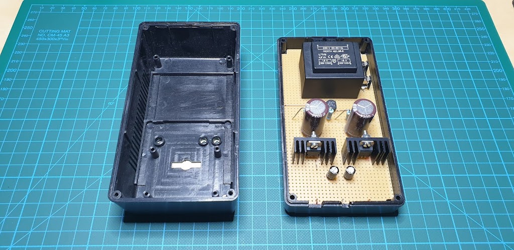
Split-rail linear power supply DC/15-0-15V.

Simple linear split-rail power supply for experiments with low power amplifiers and audio signals. This project is very easy to make and does not require a lot of time to make. But here you are working with mains voltage so you have to be very careful. 
So, if you are following along you are doing so at your own risk.

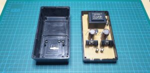
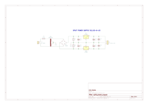
The project itself is easy to do and it is desirable to have this kind of power supply in the workshop. From the diagram shown in the image below we see that we need very few parts to make. We need the following components:
Fuse and Fuse holder,
Transformer 220V/18-0-18V,
Bridge rectifier,
Capacitor x 6 pcs,
Voltage regulator (positive and negative),
Project box,
Experiment board (PCB).
Making procedure:
First, we need to cut the experiment board (PCB) to size for fitting in our project box. Next, we are placing components and solder them to PCB connect tie-point together with a solid core wire. For the output connector, it’s recommended to use 4mm banana sockets in three different colors, for example, Black for GND, Red for +15V, and Blue for a -15V.
Stay healthy and safe till the next time!

Power supply unit, variable triple output

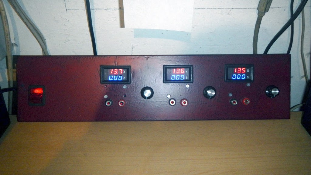
Today I finished the project, which I started a few months ago. Three channel desktop power supply with the adjustable output voltage. In the future, I would like to add control of the current limit, but I will talk about it on another occasion.

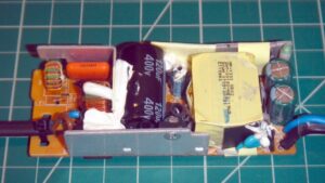
I used two adapters, from older laptops to convert AC voltage to DC. One gives 15V DC output (a little strange output, the laptop mostly uses 19V DC, but that’s what I had, so I wanted to use it) and the other gives 19V DC.

Adapter from an old laptop, AC-DC converter
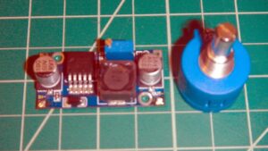
Further on, I used DC to DC (HW-411) modules purchased on eBay and 10-turn potentiometers for voltage regulation from 1.25V to 13.5V. The HW-411 is a DC-DC module with an integrated LM2596 circuit and comes with a built-in trimmer potentiometer for adjusting the output voltage. To install a 10-turn potentiometer, remove the trimmer potentiometer so that we can install a 10-turn potentiometer.
HW-411 (LM2596) DC-DC Module and 10-Turn Potentiometer
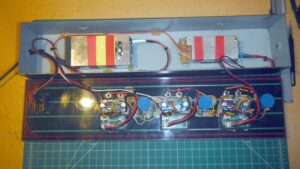
So I used three such modules and placed them on the front panel together with the panel meters, the binding post and the switch to power ON or OFF.
This is how it looks from the inside:
And that would be it, I wanted to show you how you can easily do this yourself with little effort and use old devices that usually collect dust in many homes or end up in the garbage and can still be useful.
If you choose to do this kind of device yourself, do so at your own risk. Be careful, such a device is connected to mains voltage, which can be very dangerous if you are not an expert.
All comments are welcome, thank you for visiting!

Peak voltage detector for a sine wave generator

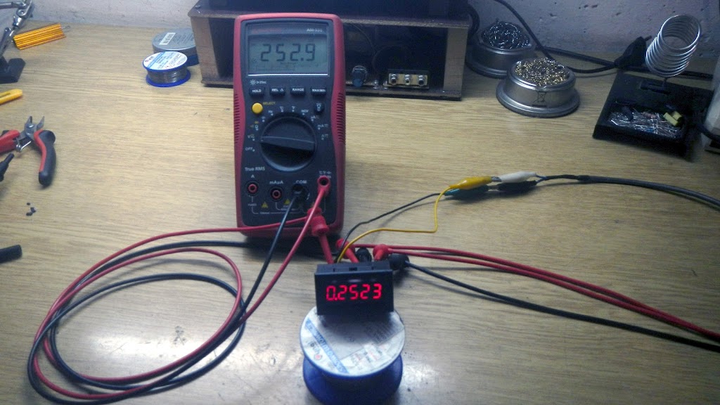
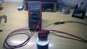
I recently built a 1kHz sine waveform generator, the device works great, has adjustable amplitude and is suitable for testing audio amplifiers and for repairing them. So I thought it would be nice if I could install a small panel voltmeter to display the output voltage.

Through eBay, I bought five voltmeters and two of them stopped working, so I decided to investigate what happened to them and try to install one of them into the sine waveform generator.
The 3.6V voltage regulator on the voltmeter itself was blown. So I removed the voltage regulator and instead of its output pin, I connected the wire to which I connected the 3.6V voltage and the voltmeter woke up.
But that’s not all, to use this kind of voltmeter to measure the voltage of the sine wave, the voltage needs to be rectified into the DC.
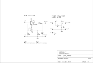
The best way to do this is by making a peak voltage detector, we can do this with uA741.
Peak voltage detector and 3.6V voltage regulator
The device works fine but has a disadvantage, it only shows a positive peak voltage so that the voltage displayed on the voltmeter. For now, I will leave the device as it is, but in the future, I plan to make a device that will spin the peak voltage of the positive and negative peak.
All comments are welcome, Thank’s for visiting!

Arduino, two channel voltmeter with thermometer

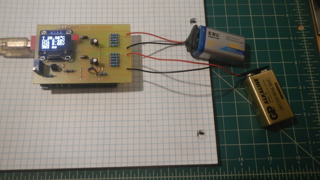
This is my new Arduino project, a two-channel voltmeter with a thermometer.
This device uses Arduino’s 10-bit analog-to-digital converter, software oversampled to 12-bit and every four measurements are added to the average value. This measured value is printed on the display every 300 milliseconds.

The scheme is not professionally and aesthetically drawn, I apologize in advance if it is unknowingly unreadable. So I will try to explain how the device works and where the input signal goes.
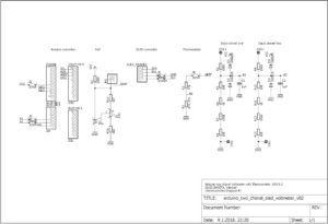
The measured voltage is applied to the input CH1 + and CH1 terminals. There are 5 resistors at the input, giving us a ratio of 10/1, which allows us to measure 40VDC voltages. The output of the voltage divide leads to the filter capacitor and protection diodes, and then to the Arduino A1 pin to be able to convert to digital format and print in the display. The same goes for channel two.
For the voltage reference, I used the TL431, which is set to give 4.096 VDC voltage and is connected to the Arduino AREF pin.
Temperature measurement was performed by a thermistor. The resistor and thermistor that are connected to the series are a voltage divider with the variable output voltage. The output is connected to the Arduino A0 pin to convert the analog value into a digital format.
The OLED display is simply connected to + 5V and GND, and signing lines SDA and SCL, to the appropriate Arduino pin.
Arduino sketch for this two-channel Voltmeter
// *********************************************************
// Program:   two chanel voltmeter with thermometer
// Date:      01/09/2018
// Version:   1.0
// Author:    Elvis Baketa
// Description: 
// *********************************************************

#include <Arduino.h>
#include <Wire.h>
#include <U8g2lib.h>

// WHITE OLED LCD 0.96" 128X64 I2C
U8G2_SSD1306_128X64_NONAME_F_HW_I2C u8g2(U8G2_R0, /* reset=*/ U8X8_PIN_NONE);

unsigned long startTime;
unsigned long finishTime;

int updateDisplay = 0;
int samples = 16;
float resolution = 4096.0;
float voltageReference = 4.096;
float seriesResistor = 47000.00;

int analogValueCH0[16];
int analogValueCH1[16];
int analogValueCH2[16];
unsigned int averageAnalogValueCH0;
unsigned int averageAnalogValueCH1;
unsigned int averageAnalogValueCH2;
float voltageCH0 = 0.000;
float voltageCH1 = 0.000;
float voltageCH2 = 0.000;
float averageVoltageCH1 = 0.000;
float averageVoltageCH2 = 0.000;

float resistance = 0.000;
float temperature = 0.000;
float averageTemperature = 0.000;

void setup() {
  // put your setup code here, to run once:
  analogReference(EXTERNAL);
  u8g2.begin();
}

void loop() {
  // put your main code here, to run repeatedly:
  updateDisplay++;
  
  // read chanel one
  for(int i = 0; i < samples; i++) {
    analogValueCH0[i] = analogRead(A0);
    delay(1);
  }
  for(int l = 0; l < samples; l++) {
    averageAnalogValueCH0 += analogValueCH0[l];
  }
  averageAnalogValueCH0 /= 4;
  voltageCH0 = averageAnalogValueCH0 * (voltageReference / resolution);
  averageAnalogValueCH0 = 0;
  // convert volts to resistance
  resistance = voltageReference / voltageCH0 - 1;
  resistance = 1 / resistance;
  resistance = seriesResistor * resistance;
  // convert resistance to temperature in Kelvin
  temperature = log(resistance / seriesResistor);
  temperature = temperature * (1 / float(3435));
  temperature = temperature + (1 / (25 + 273.15));
  temperature = 1 / temperature;
  // convert Kelvin to Celsius
  // T(°C) = T(°K) - 273.15
  temperature = temperature - 273.15;
  averageTemperature += temperature;
  
  // read chanel two
  for(int j = 0; j < samples; j++) {
    analogValueCH1[j] = analogRead(A1);
    delay(1);
  }
  for(int m = 0; m < samples; m++) {
    averageAnalogValueCH1 += analogValueCH1[m];
  }
  averageAnalogValueCH1 /= 4;
  voltageCH1 = averageAnalogValueCH1 * (voltageReference / resolution);
  voltageCH1 *= 10;
  averageVoltageCH1 += voltageCH1;
  averageAnalogValueCH1 = 0;
  
  // read chanel three
  for(int k = 0; k < samples; k++) {
    analogValueCH2[k] = analogRead(A2);
    delay(1);
  }
  for(int n = 0; n < samples; n++) {
    averageAnalogValueCH2 += analogValueCH2[n];
  }
  averageAnalogValueCH2 /= 4;
  voltageCH2 = averageAnalogValueCH2 * (voltageReference / resolution);
  voltageCH2 *= 10;
  averageVoltageCH2 += voltageCH2;
  averageAnalogValueCH2 = 0;

  if(updateDisplay > 4) {
    // display data
    u8g2.clearBuffer();
    u8g2.setFont(u8g2_font_profont22_tf);
    averageTemperature /= updateDisplay;
    u8g2.setCursor(0, 16);
    u8g2.print("T ");
    u8g2.print(averageTemperature);
    u8g2.print(char(176));
    u8g2.print("C");
    averageVoltageCH1 /= updateDisplay;
    u8g2.setCursor(0, 32);
    u8g2.print("CH1 ");
    u8g2.print(averageVoltageCH1);
    u8g2.print("V");
    averageVoltageCH2 /= updateDisplay;
    u8g2.setCursor(0, 48);
    u8g2.print("CH2 ");
    u8g2.print(averageVoltageCH2);
    u8g2.print("V");
    u8g2.setCursor(0, 64);
    finishTime = millis() - startTime;
    u8g2.print(finishTime);
    u8g2.print(" ms");
    u8g2.sendBuffer();
    averageTemperature = 0.000;
    averageVoltageCH1 = 0.000;
    averageVoltageCH2 = 0.000;
    updateDisplay = 0;
    startTime = millis();
  }
}
Here you can download Arduino sketch and Eagle PCB files to make this device.
All comments are welcome, Thank’s for visiting!

RC Filter Calculator (low-pass and high-pass)


RC Filter Calculator

Here is simple RC filter calculator for calculatie cut-off frequency of a low-pass and high-pass rc filter:

RC Filter Calculator v1.0
R = Ohm
C = Fahrad
f = Hertz

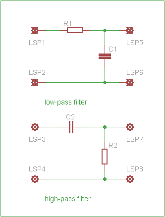
low-pass filter is a filter that passes signals with a frequency lower than a certain cutoff frequency and attenuates signals with frequencies higher than the cutoff frequency.
high-pass filter is an electronic filter that passes signals with a frequency higher than a certain cutoff frequency and attenuates signals with frequencies lower than the cutoff frequency.

More about low-pass and high-pass filer can be found on wikipedia.