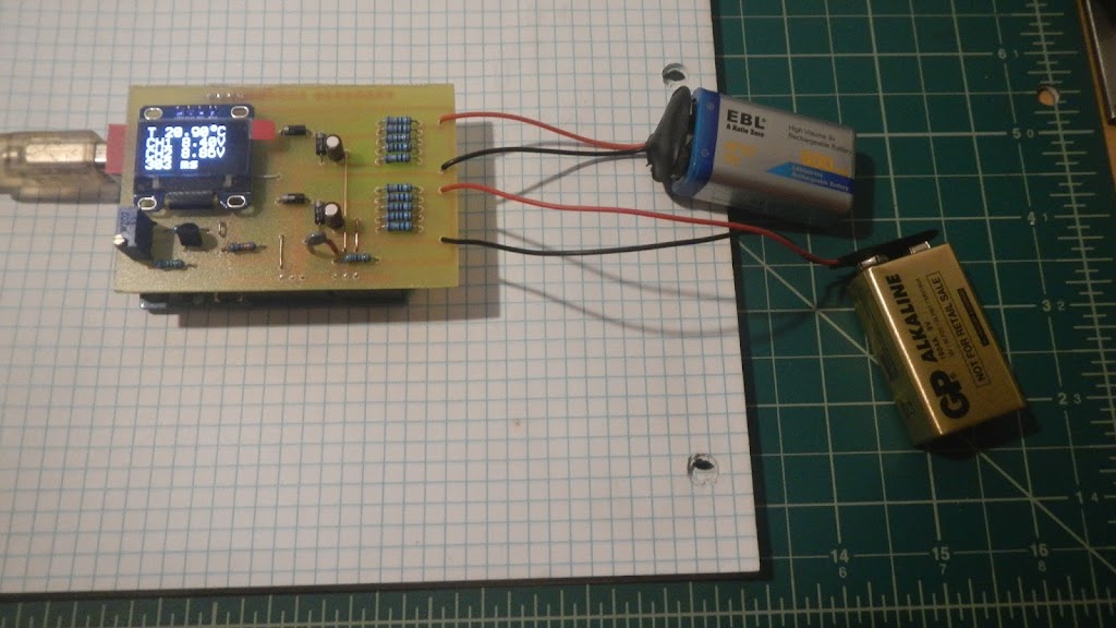
This is my new Arduino project, a two-channel voltmeter with a thermometer.
This device uses Arduino’s 10-bit analog-to-digital converter, software oversampled to 12-bit and every four measurements are added to the average value. This measured value is printed on the display every 300 milliseconds.
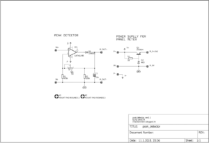
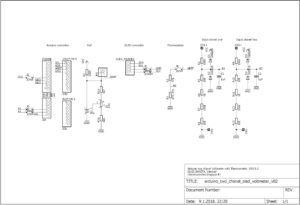
The scheme is not professionally and aesthetically drawn, I apologize in advance if it is unknowingly unreadable. So I will try to explain how the device works and where the input signal goes.
The measured voltage is applied to the input CH1 + and CH1 terminals. There are 5 resistors at the input, giving us a ratio of 10/1, which allows us to measure 40VDC voltages. The output of the voltage divide leads to the filter capacitor and protection diodes, and then to the Arduino A1 pin to be able to convert to digital format and print in the display. The same goes for channel two.
For the voltage reference, I used the TL431, which is set to give 4.096 VDC voltage and is connected to the Arduino AREF pin.
Temperature measurement was performed by a thermistor. The resistor and thermistor that are connected to the series are a voltage divider with the variable output voltage. The output is connected to the Arduino A0 pin to convert the analog value into a digital format.
The OLED display is simply connected to + 5V and GND, and signing lines SDA and SCL, to the appropriate Arduino pin.
Arduino sketch for this two-channel Voltmeter
// *********************************************************
// Program:   two chanel voltmeter with thermometer
// Date:      01/09/2018
// Version:   1.0
// Author:    Elvis Baketa
// Description:
// *********************************************************

#include <Arduino.h>
#include <Wire.h>
#include <U8g2lib.h>

// WHITE OLED LCD 0.96" 128X64 I2C
U8G2_SSD1306_128X64_NONAME_F_HW_I2C u8g2(U8G2_R0, /* reset=*/ U8X8_PIN_NONE);

unsigned long startTime;
unsigned long finishTime;

int updateDisplay = 0;
int samples = 16;
float resolution = 4096.0;
float voltageReference = 4.096;
float seriesResistor = 47000.00;

int analogValueCH0[16];
int analogValueCH1[16];
int analogValueCH2[16];
unsigned int averageAnalogValueCH0;
unsigned int averageAnalogValueCH1;
unsigned int averageAnalogValueCH2;
float voltageCH0 = 0.000;
float voltageCH1 = 0.000;
float voltageCH2 = 0.000;
float averageVoltageCH1 = 0.000;
float averageVoltageCH2 = 0.000;

float resistance = 0.000;
float temperature = 0.000;
float averageTemperature = 0.000;

void setup() {
  // put your setup code here, to run once:
  analogReference(EXTERNAL);
  u8g2.begin();
}

void loop() {
  // put your main code here, to run repeatedly:
  updateDisplay++;

  // read chanel one
  for(int i = 0; i < samples; i++) {
    analogValueCH0[i] = analogRead(A0);
    delay(1);
  }
  for(int l = 0; l < samples; l++) {
    averageAnalogValueCH0 += analogValueCH0[l];
  }
  averageAnalogValueCH0 /= 4;
  voltageCH0 = averageAnalogValueCH0 * (voltageReference / resolution);
  averageAnalogValueCH0 = 0;
  // convert volts to resistance
  resistance = voltageReference / voltageCH0 - 1;
  resistance = 1 / resistance;
  resistance = seriesResistor * resistance;
  // convert resistance to temperature in Kelvin
  temperature = log(resistance / seriesResistor);
  temperature = temperature * (1 / float(3435));
  temperature = temperature + (1 / (25 + 273.15));
  temperature = 1 / temperature;
  // convert Kelvin to Celsius
  // T(°C) = T(°K) - 273.15
  temperature = temperature - 273.15;
  averageTemperature += temperature;

  // read chanel two
  for(int j = 0; j < samples; j++) {
    analogValueCH1[j] = analogRead(A1);
    delay(1);
  }
  for(int m = 0; m < samples; m++) {
    averageAnalogValueCH1 += analogValueCH1[m];
  }
  averageAnalogValueCH1 /= 4;
  voltageCH1 = averageAnalogValueCH1 * (voltageReference / resolution);
  voltageCH1 *= 10;
  averageVoltageCH1 += voltageCH1;
  averageAnalogValueCH1 = 0;

  // read chanel three
  for(int k = 0; k < samples; k++) {
    analogValueCH2[k] = analogRead(A2);
    delay(1);
  }
  for(int n = 0; n < samples; n++) {
    averageAnalogValueCH2 += analogValueCH2[n];
  }
  averageAnalogValueCH2 /= 4;
  voltageCH2 = averageAnalogValueCH2 * (voltageReference / resolution);
  voltageCH2 *= 10;
  averageVoltageCH2 += voltageCH2;
  averageAnalogValueCH2 = 0;

  if(updateDisplay > 4) {
    // display data
    u8g2.clearBuffer();
    u8g2.setFont(u8g2_font_profont22_tf);
    averageTemperature /= updateDisplay;
    u8g2.setCursor(0, 16);
    u8g2.print("T ");
    u8g2.print(averageTemperature);
    u8g2.print(char(176));
    u8g2.print("C");
    averageVoltageCH1 /= updateDisplay;
    u8g2.setCursor(0, 32);
    u8g2.print("CH1 ");
    u8g2.print(averageVoltageCH1);
    u8g2.print("V");
    averageVoltageCH2 /= updateDisplay;
    u8g2.setCursor(0, 48);
    u8g2.print("CH2 ");
    u8g2.print(averageVoltageCH2);
    u8g2.print("V");
    u8g2.setCursor(0, 64);
    finishTime = millis() - startTime;
    u8g2.print(finishTime);
    u8g2.print(" ms");
    u8g2.sendBuffer();
    averageTemperature = 0.000;
    averageVoltageCH1 = 0.000;
    averageVoltageCH2 = 0.000;
    updateDisplay = 0;
    startTime = millis();
  }
}
Here you can download
Arduino sketch and
Eagle PCB files to make this device.
All comments are welcome, Thank’s for visiting!
