Programing AT89C2051 using SDCC compiler on Debian Linux

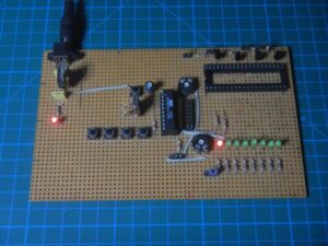
My Homemade AT89C2051 Development Board

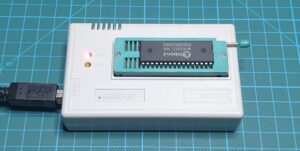
First and foremost we need to install a compiler and we need a programmer to load the code into the microcontroller. In my case, I use TL866A Universal Programmer.

SDCC
minipro

So let’s start with the installation of the compiler:

// install SDCC package:
apt install sdcc

// test instalation
sdcc --version

TL866A Universal Programmer

The next step is to install the programmer software:

// install dependencies for minipro
apt install build-essential pkg-config git libusb-1.0-0-dev

// get source code of minipro
git clone https://gitlab.com/DavidGriffith/minipro.git

// compile minipro software
cd minipro
make

// install application
sudo make install

// udev configuration
sudo cp udev/*.rules /etc/udev/rules.d/
sudo udevadm trigger

// add user to the plugdev group
sudo usermod -a -G plugdev YOUR-USER

// test instalation
minipro --version

For this occasion, I wrote the Blink c program for AT89C2051 and compiled it using SDCC on Debian Linux.

// ********************************************************
// Program:     Blink LED example
// Author:      Elvis Baketa
// Processor:   AT89C2051
// Oscillator:  12 MHz
// Compiler:    SDCC (Linux)
// Version:     0.1
// Comment:     
// ********************************************************

#include "at89x051.h"

// declare function
void delayms(void);
void delay(int data);

// main function
void main(void)
{
    // declare variable
    int i = 0;
    
    // run once
    P1_0 = 1;
    
    // loop forever
    while(1)
    {
        // turn LED on
        P1_0 = 0;
        // wait 1 second
        delay(1000);
        // turn LED off
        P1_0 = 1;
        // wait 1 second
        delay(1000);
    }
}

// delay one milisecond
void delayms(void)
{
    int i;
    // count to 33 for 1 ms delay
    for (i = 0; i < 34; i++);
}

// amount of milisecond to delay
void delay(int data)
{
    int i;
    for (i = 0; i < data; i++)
    {
        delayms();
    }
}

You can find source code on GitHub repo blink at89c2051.

Until next time.
RND (KORAD) DC Power Supply Control (Work in Progress)

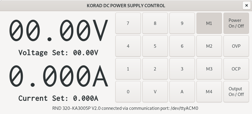
I am currently learning to program in the Python programming language on a Linux operating system and I can tell you that it is fun. It’s simple and I’m starting to turn my ideas into works, like this example here, controlling electronics using a PC and automating measurements.

The application is currently under construction. For now, I have designed a graphical interface in Glade (Glade is A user interface designer for GTK+ and GNOME) and implemented a serial port connection function.

The goal is to write a complete application for controlling, automating measurements, and saving data to a file, and perhaps a draw graph representation. I am currently testing the application on a PC with Debian Linux OS but I believe it is possible to use it on a Raspberry Pi OS as well.

The whole idea of this project is to learn how to apply Python to automate the measurement and control of electronic devices. One option is to control the Arduino, read digital multimeter measurements and the list goes on.

Github repo: https://github.com/ebaketa/rnd_320-ka3005p

Till the next time!

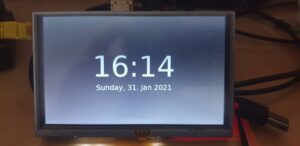
Raspberry Pi Digital Clock, written in Python programming language

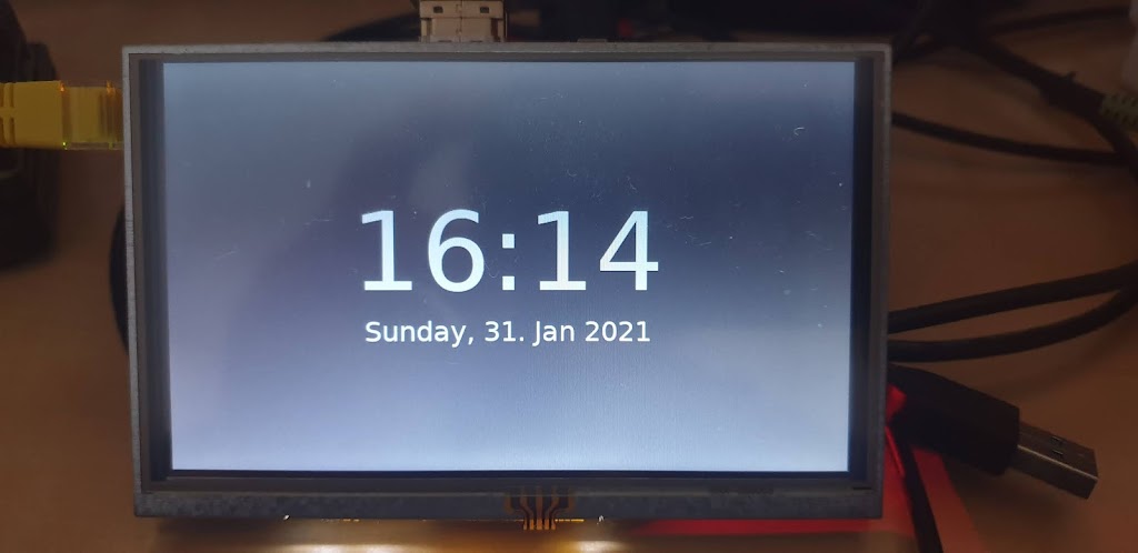
This was challenging for me to get into Python programming and setting Raspberry Pi to my own needs. I know this is overkill but also this is a path for future projects for example info display which can display time, the temperature in your place, and maybe turn on lights in the living room and the list goes on and on.

Hardware requirements:

Raspberry Pi
Waveshare 5inch HDMI LCD
MicroSD Card
PSU for Raspberry Pi

1. create micro sd card with raspberry pi os lite

Here we need to enter the path and name of the image we want to write to the sd card instead of “/ source_image_file” and instead of “/ destination_disk_drive” we need to enter the path and name of the disk we want to write to.

sudo dd if=/source_image_file of=/destination_disk_drive

2. enable SSH

To be able to access over SSH we need to create an empty file named SSH in the boot partition of our Micro SD card.

sudo touch /media/your_username/boot/SSH

3. setup hostname

sudo nano /media/ebaketa/rootfs/etc/hostname

4. edit the host’s file and replace “myhostname” with the desired hostname:

sudo nano /media/your_username/rootfs/etc/hosts

127.0.0.1	localhost
::1		localhost
127.0.1.1	myhostname.localdomain	myhostname

5. setup a static IP address

sudo nano /media/your_username/rootfs/etc/dhcpcd.conf

# Example static IP configuration:
interface eth0
static ip_address=192.168.x.xxx/24
#static ip6_address=fd51:42f8:caae:d92e::ff/64
static routers=192.168.x.x
static domain_name_servers=192.168.x.x 8.8.8.8 fd51:42f8:caae:d92e::1

6. edit Raspberry Pi OS configuration file config.txt

These lines below we need to add to “config.txt” to configure 5 inch HDMI LCD. The best is to add lines to the end of the file.

max_usb_current=1
hdmi_group=2
hdmi_mode=87
hdmi_cvt 800 480 60 6 0 0 0
hdmi_drive=1

7. insert micro SD to the target machine, boot OS, and login over SSH

Now we can insert an SD card into Raspberry Pi, connect the power supply and boot into OS.

8. update Raspberry Pi OS

sudo apt update
sudo apt upgrade

9. reboot Raspberry Pi OS and login over SSH

10. start raspi-config tool

sudo raspi-config

change default password
set boot options -> console autologin
set language and regional settings
set keyboarad layout
set time zone

11. reboot Raspberry Pi OS and login over SSH

12. install xorg, xinit, x11-server-utils

sudo apt -y install --no-install-recommends xserver-xorg
sudo apt -y install --no-install-recommends xinit
sudo apt -y install x11-xserver-utils

13. install openbox, lxterminal, lxtask, lxappearance

sudo apt -y install openbox obconf obmenu lxterminal lxtask lxappearance

14. install PyGObject

sudo apt -y install python-gi python-gi-cairo python3-gi python3-gi-cairo gir1.2-gtk-3.0

15. create .bash_profile file and add a line below

touch ~/.bash_profile && sudo nano ~/.bash_profile

if [[ -z $DISPLAY ]] && [[ $(tty) = /dev/tty1 ]]; then exec startx; fi

16. create openbox autostart file and add lines below

mkdir ~/.config && mkdir ~/.config/openbox && touch ~/.config/openbox/autostart && sudo nano ~/.config/openbox/autostart

# disable screen saver
xset s off &
xset s -dpms &
# run python digital clock
python ~/Projects/python/digital_clock/digital_clock.py

17. create directories for projects and get projects via wget

mkdir ~/Projects && mkdir ~/Projects/python && mkdir ~/Projects/python/digital_clock && cd ~/Projects/python/digital_clock

wget https://raw.githubusercontent.com/ebaketa/digital_clock/master/digital_clock.py

18. reboot Raspberry Pi OS

And that’s it with the next boot you should have a Raspberry Pi digital clock. If you find any mistakes in commands, please let me know, so I can correct them!

Github repo: https://github.com/ebaketa/digital_clock

Till the next time!

Install dmenu from source code on Raspberry Pi

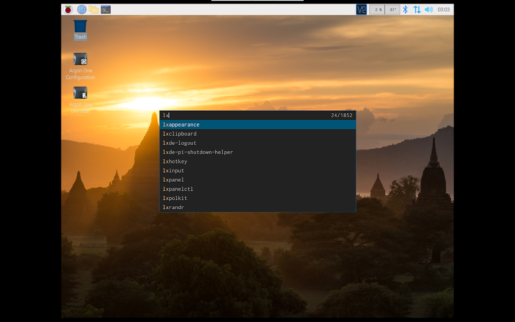
So what is dmenu? dmenu is a dynamic menu for the X Window System and Raspberry Pi runs Linux. It is simple and can manage large numbers of user-defined menu items efficiently. And one more thing you need to install it from the source code so it is a good exercise to learn how to compile a program in Linux.

dmenu configured to show up in the middle of the screen


Software is freely available from suckless.org, and there is also “dwm” windows manager for X, “st” simple terminal, “surf” simple web browser, and more.
dmenu configured to show up on the top of the screen

First, we need to update the system and install dependencies:

sudo apt update
sudo apt install xorg-dev
sudo apt install build-essential
sudo apt install git

Clone dmenu git repo:

git clone https://git.suckless.org/dmenu

Change directory:

cd dmenu

Build and install dmenu:

sudo make install

And we are ready to run dmenu from the terminal and use it. It shows up above on top of the panel. But it is smaller than the panel and there are fever patches that can help us to look better.

Remove compiler output files:

sudo make clean

Removing config.h file helps to apply patches:

sudo rm config.h

Download desired patch:

// numbers
wget https://tools.suckless.org/dmenu/patches/numbers/dmenu-numbers-4.9.diff
patch -p1 < dmenu-numbers-4.9.diff
sudo make install
sudo make clean
sudo rm config.h

// center
wget https://tools.suckless.org/dmenu/patches/center/dmenu-center-20200111-8cd37e1.diff
patch -p1 < dmenu-center-20200111-8cd37e1.diff
sudo make install
sudo make clean
sudo rm config.h

// highlight
wget https://tools.suckless.org/dmenu/patches/highlight/dmenu-highlight-20201211-fcdc159.diff
patch -p1 < dmenu-highlight-20201211-fcdc159.diff
sudo make install
sudo make clean
sudo rm config.h

// line height
wget https://tools.suckless.org/dmenu/patches/line-height/dmenu-lineheight-5.0.diff
patch -p1 < dmenu-lineheight-5.0.diff
sudo make install
sudo make clean
sudo rm config.h

// border
wget https://tools.suckless.org/dmenu/patches/border/dmenu-border-4.9.diff
patch -p1 < dmenu-border-4.9.diff
sudo make install
sudo make clean
sudo rm config.h

With this part of the setup, we are gonna create keybindings for an easy run as a top panel or in the middle of the screen.

Edit Raspberry Pi OS keybindings:

sudo nano /etc/xdg/openbox/lxde-pi-rc.xml

Add this lines in <keyboard> section:

<keybind key="C-S-space">
    <action name="Execute">
        <command>dmenu_run -h 36</command>
    </action>
</keybind>
<keybind key="C-space">
    <action name="Execute">
        <command>dmenu_run -h 30 -c -l 10</command>
    </action>
</keybind>

Now if we press a key combination SHIFT + CTRL + SPACE runs dmenu above the top panel and pressing CTRL + SPACE runs dmenu in the middle of the screen. And that all for this late-night adventure with Raspberry Pi.

Till the next time.

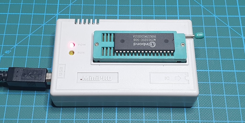
MiniPRO TL866xx universal programmer Linux installation.

The TL866A universal programmer is a chip programmer that allows us to write or read chip memory such as microcontrollers, EEPROM memory, etc. This very popular device, unfortunately, comes with software only for the Windows operating system. But there is an open-source alternative that allows the use of this device on the Linux operating system, thanks to David Griffith and his project on GitLab.


Installation:

Install build dependencies:

sudo apt install build-essential pkg-config git libusb-1.0-0-dev

Get source code:

git clone https://gitlab.com/DavidGriffith/minipro.git

Compile source code:

cd minipro
make

Install application:

sudo make install

Udev configuration:

sudo cp udev/*.rules /etc/udev/rules.d/
sudo udevadm trigger

Add regular user to the plugdev group:

sudo usermod -a -G plugdev YOUR-USER

Reboot your system.

Basic usage:

Show all available options:

minipro

Show version information:

minipro -V

Read from the device and save to a file:

minipro -p W29C020C -r test_w29c020c.bin

Erase the device:

minipro -p W29C020C -E

Blank check:

minipro -p W29C020C -b

Write from file to the device:

minipro -p W29C020C -w test_w29c020c.bin

I am very pleased with this installation, everything went without a single problem and the universal programmer works flawlessly. Many thanks to the open-source community and fingers up for David’s project on GitLab.

Stay healthy and safe till the next time!

Basic commands and using PICkit 2 on Linux!

Now that we have the software installed and ready to use, it is time to get familiar with the basic commands to successfully load the program into the microcontroller. So let’s get started!

Checking version:

pk2cmd -?V

# Returned output:

Executable Version:    1.20.00
Device File Version:   1.55.00
OS Firmware Version:   2.32.00


Operation Succeeded

Auto-detect PIC:

pk2cmd -P

# Returned output:
Auto-Detect: Found part PIC16F887.


Operation Succeeded

Erase a device:

pk2cmd -P -E

# Returned output:
Auto-Detect: Found part PIC16F887.

Erasing Device...

Operation Succeeded

Blank check:

pk2cmd -P -C

# Returned output:
Auto-Detect: Found part PIC16F887.

Device is blank

Operation Succeeded

Program a device:

pk2cmd -PPIC16F887 -J -M -Ftest_write.hex

# Returned output:
PICkit 2 Program Report       
2-1-2021, 1:17:27
Device Type: PIC16F887

Program Succeeded.

Operation Succeeded

Power a device and release reset:

pk2cmd -P -A5 -T -R

# Returned output:
Auto-Detect: Found part PIC16F887.


Operation Succeeded

Read a device:

pk2cmd -PPIC16F887 -J -R -GFtest_read.hex

# Returned output:
Read successfully.            

Operation Succeeded
I believe this is enough to get started with PICkit 2 Development Programmer / Debugger on Linux OS.
Stay healthy and safe till the next time!

Install PICkit 2 Development Programmer / Debugger on Raspberry Pi OS.

To install PICkit 2 Development Programmer / Debugger on Raspberry Pi OS, we are gonna first prepare our system by installing dependencies, download source code for PICkit 2 command-line application, compile it, and at the end verify test installation.

So for that, we are gonna use these commands as follows:

Update and Install dependencies:

sudo apt update
sudo apt install build-essential libusb-dev

Download and unpack the source files:

wget https://ww1.microchip.com/downloads/en/DeviceDoc/pk2cmdv1.20LinuxMacSource.tar.gz
tar xzvf pk2cmdv1.20LinuxMacSource.tar.gz
cd pk2cmdv1.20LinuxMacSource

Building the application:

make linux

Installing the application:

make install

Adding device file location to PATH:

echo 'export PATH="$PATH:/usr/share/pk2"' >> ~/.bashrc

Reboot system and test installation:

pk2cmd -?v

# PICki2 not connected
Executable Version:    1.20.00
Device File Version:   1.55.00
OS Firmware Version:   PICkit 2 not found

# PICkit2 connected
Executable Version:    1.20.00
Device File Version:   1.55.00
OS Firmware Version:   2.32.00

Uninstall pk2cmd:

Remove file pk2cmd from /usr/local/bin:
sudo rm -R /usr/local/bin/pk2cmd

Remove all files from /usr/share/pk2/:
sudo rm /usr/share/pk2/*

Remove folder /usr/share/pk2/:
sudo rm -R /usr/share/pk2

Edit file .bashrc:
sudo nano ~/.bashrc

Find and Remove line :
export PATH="$PATH:/usr/share/pk2"

Stay healthy and safe till the next time!

Install PICkit 2 Development Programmer / Debugger on Debian 10 Buster 64-bit.

To install PICkit 2 Development Programmer / Debugger on Debian 10 Buster 64-bit, we need to install library packages for i386 architecture. That we can do with Multiarch. What is Multiarch? Multiarch lets us install library packages from multiple architectures on the same machine.

So for that, we are gonna use a couple of commands to print current architecture, check foreign architecture, and add a new architecture.

The first command is gonna print the current machine architecture:

dpkg --print-architecture
amd64

The second command is gonna print foreign machine architecture. If print nothing, means we don’t have foreign machine architecture added to our system:

dpkg --print-foreign-architectures

The next step is a way to add foreign machine architecture to our system:

dpkg --add-architecture i386

So now if we do check for other available architectures, it should print i386:

dpkg --print-foreign-architectures
i386

Now we need to install dependencies for compiling our source files:

sudo apt update
sudo apt install build-essential libusb-dev

That’s all for preparing the system. The next step is downloading and unpacking the source files:

wget https://ww1.microchip.com/downloads/en/DeviceDoc/pk2cmdv1.20LinuxMacSource.tar.gz
tar xzvf pk2cmdv1.20LinuxMacSource.tar.gz
cd pk2cmdv1.20LinuxMacSource

Building the application:

make linux

Installing the application:

make install

Adding device file location to PATH:

echo 'export PATH="$PATH:/usr/share/pk2"' >> ~/.bashrc

Reboot system and test installation:

pk2cmd -?v

# PICki2 not connected
Executable Version:    1.20.00
Device File Version:   1.55.00
OS Firmware Version:   PICkit 2 not found

# PICkit2 connected
Executable Version:    1.20.00
Device File Version:   1.55.00
OS Firmware Version:   2.32.00

Uninstall pk2cmd:

Remove file pk2cmd from /usr/local/bin:
sudo rm -R /usr/local/bin/pk2cmd

Remove all files from /usr/share/pk2/:
sudo rm /usr/share/pk2/*

Remove folder /usr/share/pk2/:
sudo rm -R /usr/share/pk2

Edit file .bashrc:
sudo nano ~/.bashrc

Find and Remove line :
export PATH="$PATH:/usr/share/pk2"

Stay healthy and safe till the next time!

Split-rail linear power supply DC/15-0-15V.

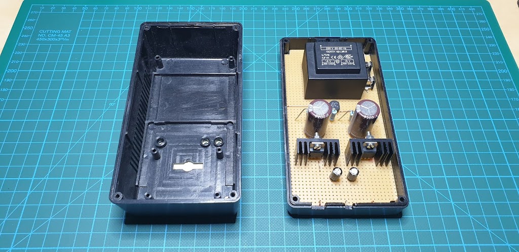
Simple linear split-rail power supply for experiments with low power amplifiers and audio signals. This project is very easy to make and does not require a lot of time to make. But here you are working with mains voltage so you have to be very careful. 
So, if you are following along you are doing so at your own risk.

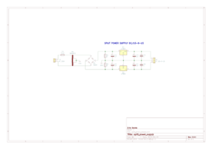
The project itself is easy to do and it is desirable to have this kind of power supply in the workshop. From the diagram shown in the image below we see that we need very few parts to make. We need the following components:
Fuse and Fuse holder,
Transformer 220V/18-0-18V,
Bridge rectifier,
Capacitor x 6 pcs,
Voltage regulator (positive and negative),
Project box,
Experiment board (PCB).
Making procedure:
First, we need to cut the experiment board (PCB) to size for fitting in our project box. Next, we are placing components and solder them to PCB connect tie-point together with a solid core wire. For the output connector, it’s recommended to use 4mm banana sockets in three different colors, for example, Black for GND, Red for +15V, and Blue for a -15V.
Stay healthy and safe till the next time!

Amazing RPi 4 setup with 250GB SSD and 1.5TB storage space!

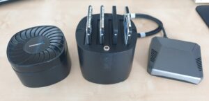
Of course, this is not the best and most powerful setup but it is an interesting
solution. All these hard drives I have laying around so I decided to
use them and it is a great addition to Raspberry Pi 4.

So what we do have here:
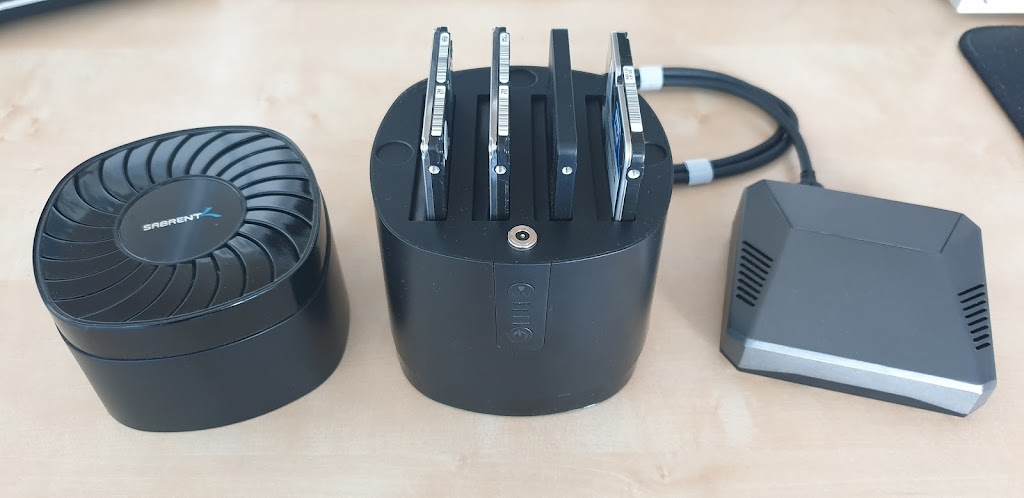
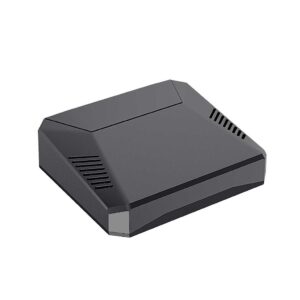
The first component here is the case for Raspberry Pi 4, Argon One. Very well design aluminum case with controlled fan for cooling and power on/off button. The fan has a little bit annoying sound. This housing is excellent for overclocking Raspberry Pi 4, I’m running all day on 2 GHz without any problem.
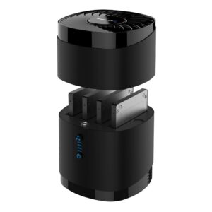
The second piece of the puzzle is a USB 3.0 hard drive docking station. Sabrent USB
3.0 4 Bay 2.5″ Hard Drive/SSD Docking Station with Fan. This is excellent for the system drive and for storage. In my system, I’m having 250 GB SSD for
system and programs and three 500 GB hard drives for storage.
I’m pretty happy with this setup, fast boot over SSD and enough space for
storage.
Thanks for visiting!
Till the next time.